
The concrete wall panel element allows you to easily model, analyze, and design concrete walls for in plane loads for the codes defined below:
Note:
Here we will explain the concrete-specific inputs and design considerations. For general wall panel information, see the Wall Panels topic. For concrete wall design rule information, see the Concrete Wall - Design Rules topic. For concrete wall results interpretation, see the Concrete Wall Results topic.
Double-click on the wall from the model view to open the Wall Panel Editor. This dialog displays input information such as Material and Design Rule, as well as gives viewing options for Region and reinforcement display (after solution). Within this dialog you also have control over the application of continuous boundary conditions.
Concrete wall panels have the following view controls:
 Toggle Region display allows you to turn the display of regions on or off.
 Toggle Lintel display allows you to turn the display of lintels on or off.
 Toggle Reinforcement display allows you to turn the display of reinforcement on or off after you have solved your model.
Concrete walls depend on Regions for results presentation. The program automatically creates these regions at solution time. If you have a wall panel with no
Within each region, the program will optimize the spacing of bars for strength, spacing and minimum reinforcement considerations of the wall.
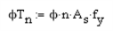
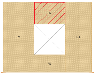
From within the Wall Panel Editor, you have the option of creating rectangular regions within the concrete wall panel. Regions are used to define reinforcement in different parts of the wall. Each region will be assigned a uniform reinforcement, which may be different than the reinforcement in other parts of the same wall (unless you are using Group Story option from Wall Design Rules).
If no regions have been drawn on a wall then they will be automatically generated when a solution is performed. To automatically generate regions prior to running a solution, click the
To manually draw regions, select the 
The program will design the reinforcement spacing for you. For this design reinforcement spacing, rho, and strength requirements are considered for design. If specific reinforcement is defined in the Wall Design Rules spreadsheet then it may be possible for the reinforcement design to not meet code requirements.
Sections 25.2 and Chapter 11 have provisions regarding min/max spacing, required reinforcement ratios, and proper proportioning of wall reinforcement. If your wall does not meet a code requirement the program will give a red warning message in the detail report.
Section 25.2 (General Reinforcement Requirements)
The minimum spacing requirements from Section 25.2.1 are considered for design.
Chapter 11 (Wall Reinforcement Detailing)
The maximum spacing requirements from section 11.7.2.1 and 11.7.3.1 are considered for design.
Note:
The minimum spacing requirements of Section 11.6.1 are also considered for design. Additionally, the thickness requirement from Section 11.7.2.3 as well as the proportioning and cover checks in that section are also considered.
The program will consider the reinforcement requirements of Section 11.6.2 if the Vu exceeds 0.5*ϕ*Vc.
The program will design the reinforcement spacing for you. For this design reinforcement spacing, rho, and strength requirements are considered for design. If specific reinforcement is defined in the Wall Design Rules spreadsheet then it may be possible for the reinforcement design to not meet code requirements.
Sections 7.6, 14.3 and 11.9 all have provisions regarding min/max spacing, required reinforcement ratios, and proper proportioning of wall reinforcement. If your wall does not meet a code requirement the program will then give you a red warning message in the detail report.
Section 7.6 (General Reinforcement Requirements)
The minimum spacing requirements from 7.6.1 and the maximum spacing requirements from section 7.6.5 are considered for design.
Section 14.3 (Wall Reinforcement Requirements)
The minimum spacing requirements of Sections 14.3.2 and 14.3.3 and maximum spacing requirements of 14.3.5 are also considered for design. Additionally, the thickness requirement from Section 14.3.4 as well as the proportioning and cover checks of 14.3.4 are also considered.
Section 11.9.8 and 11.9.9 (Shear Reinforcement Requirements for Walls)
The program will consider the reinforcement requirements of Section 11.9.9 if the Vu exceeds 0.5*ϕ*Vc (per Section 11.9.8).
The program will design the reinforcement spacing for you. For this design reinforcement spacing, rho, and strength requirements are considered for design. If specific reinforcement is defined in the Wall Design Rules spreadsheet then it may be possible for the reinforcement design to not meet code requirements.
Clause 14.1.7.1 and 14.1.8 have provisions regarding wall geometry, min/max spacing, required reinforcement ratios, and proper proportioning of wall reinforcement. If your wall does not meet a code requirement the program will then give you a red warning message in the detail report.
Clause 14.1.7.1 (General Wall Geometry Requirements)
The thickness of the walls shall be not less than the smaller of lw / 25 or hu / 25, but not less than 150 mm.
Clause 14.1.8 (Wall Reinforcement Requirements)
The program considers the provisions for reinforcement diameter (14.1.8.2), number of layers (14.1.8.3), max spacing of reinforcement (14.1.8.4), and min reinforcement ratio (14.1.8.5 & 14.1.8.6).
The reinforcement is designed to meet spacing, rho, and strength requirements. This design may cause the reinforcement spacing design to not fit in the wall region at the exact spacing designed for. Therefore the program will add bars to the extreme ends of the wall region to take these remainders into account.
The reinforcement layout algorithm works as follows (picture looking down on a cross section of wall):
First the required spacing is calculated and the wall region length is divided by this spacing.
Note:

The axial tensile capacity for a wall assumes all reinforcement is fully developed. The capacity (with no bending interaction) equals:
where n = number of vertical bars in the wall.
The axial compressive capacity (with no bending interaction) is taken from equation 10-2.
If CSA A23.3-14 code is selected, Clause 10.10.4 was used to calculate the axial compressive capacity (with no bending interaction).
Note:
ACI 318-14 Section 6.6.4.5.4 (ACI 318-11 Section 10.10.6.5) requires a minimum required moment to be taken into account. Thus, if the value from ACI 318-14 Eq 6.6.4.5.4 (ACI 318-11 Eq 10-17) is greater than the calculated moment demand this value will be used. This is meant to account for a minimum eccentricity of the axial force in the wall. CSA A23.3-14 has similar requirements on minimum required moment as defined in 10.15.3.1.
The design moment may be factored up due to P-Little Delta effects (see below).
When ACI 318-19 is selected, Vc is calculated using Equation 11.5.4.3. For wall panels subjected to net axial tension, αs is calculated using Equation 11.5.4.4.
When other ACI 318 editions are selected, Vc is taken into account using ACI 318-14 Detailed Equations from Table 11.5.4.6 (ACI 318-11 Equations 11-27 and 11-28), where:
When CSA A23.3-14 are selected, Vc is taken into account using Equation 11.6. The factor β is calculated using Equation 11.11 where:
Vs is taken from ACI 318-14 Equation 11.5.4.8 (ACI 318-11 Equation 11-29). Although Vs is only required if Vu >= 0.5*ϕ*Vc, any minimum reinforcement requirement will be used as Vs and added to the shear capacity.
Note:
When CSA A23.3-14 are selected, Vs is taken from Equation 11.7 where the angle of inclination θ is calculated using Equation 11.12.
When ACI 318-19 is selected, Vc is calculated using Equation (c) in Table 22.5.5.1. Note that ACI 318-19 code suggests ρw may be taken as the sum of the areas of longitudinal bars located more than two-thirds of the overall member depth away from the extreme compression fiber. Therefore, RISA calculates ρw as the sum of the areas of vertical bars on the tension face.
When other ACI 318 editions are selected, the equations from ACI 318-14 Sections 22.5.6.1 and 22.5.7.1 (ACI 318-11 Section 11.2.15 and 11.2.3) is used for Vc.
When CSA A23.3-14 are selected, Vc is calculated in the same way as In-Plane shear section.
Lambda is considered differently for the 2005 and newer codes. For ACI 318-05 the program will always consider lambda = 0.75 if the Density of concrete is <= 115 pcf and lambda = 1.0 otherwise (ACI 318-05 Section 11.2.1). For the ACI 318-08 and newer codes, the program will use the Lambda value directly from the Materials spreadsheet.
The deflection listed in the detail report is based on the finite element analysis of plate elements. This deflection agrees well with beam theory, thus can be calculated based on beam equations.
Note:

The program uses a concrete solver to create the interaction diagram and uses this diagram to calculate the capacity of a wall/wall region based on the demand axial force and moment. The program computes the code check based on making a straight line through the origin, the moment/axial force demand location, and where that line crosses the interaction diagram curve.
The program will ignore axial forces and moments that are below a certain threshold. If the moment or axial force is deemed to be inconsequential to the code check then the program will simply not include the interaction of that force. There are two thresholds that are considered:
These two thresholds allow the concrete solver to work much more efficiently while having little to no effect on code check values.
Per ACI 318-14 Section 6.7.1.1 (ACI 318-11 Section 10.10.4) an elastic second order analysis will satisfy code requirements. In RISA this means running a P-Delta analysis to consider secondary moments induced due to the displacement of member ends and a P-Little Delta analysis to account for member curvature effects.
The ACI 318-14 requires that either Section 6.6.4, 6.7 or 6.8 are used for sway frames. The ACI 318-08/11 specifications require that either Section 10.10.3, 10.10.4 or 10.10.5 are used. The ACI 318-05 specification requires that you follow provisions of Section 10.13.
Because a P-Delta analysis (big and little) is a more robust analysis the program requires this analysis for all ACI specifications.
The secondary effects due to the displacements of member ends is taken into account with the inclusion of a P-Delta analysis.
To perform a P-Delta Analysis place a "Y" in the P-Delta column of the Load Combinations spreadsheet. For more information on this, see P-Delta .
The design moment (max of demand moment and minimum required moment) must be factored up per ACI 318-14 Section 6.6.4.5 (ACI 318-11 Section 10.10.6) if the wall is considered slender.
Slenderness requirements are given in ACI 318-14 Section 6.2.5 (ACI 318-11 Section 10.10.1). The program conservatively only considers ACI 318-14 Equation 6.2.5.a (ACI 318-11 Equation 10-6). Thus, if the KL/r (in either direction) exceeds 22, then the provisions of ACI 318-14 Section 6.6.4.5 (ACI 318-11 Section 10.10.6) are also considered. CSA A23.3-14 uses the same procedure in considering the P-Little Delta effect.
Note:
The addition of openings into a wall in the wall panel editor will automatically create a lintel above the opening. It will be symbolized by a blue bar that has the name of the lintel inside of it. The program will produce axial, shear and moment diagrams for the lintel that can be viewed from the Concrete Wall Detail Report from the Lintel drop-down option. Here we will explain some of the different considerations.
In RISA-3D the lintel is considered as the entire region directly above an opening (L1 below), even though the blue bar does not cover this entire area.
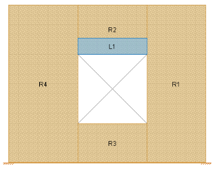
At solution the program will then perform a summation of forces over this entire region and presents the analysis results in the detail report. These results are presented as a "beam" analysis. The program will cut through the entire region vertically multiple times along the length of the region. At each cut the program will calculate the axial, shear and moments. The results from each of these cuts are then combined to form the force diagrams.
Note:
See the
The program will use the Wall Design Rules and start with the maximum spacing and check that configuration for strength, spacing, and minimum reinforcing requirements. If the max spacing works, then the design is done. If not then the program will reduce the spacing by the spacing increment and then do the same checks. This will occur until a bar spacing is reached to satisfy the code requirements.